
1. 19,000 tons of the spent nuclear fuel
There are two ways to store the spent nuclear fuel, cooling pool and dry cask.
The minimum depth for the cooling pool is 6 meters, but usually it is 12 meters. The water has the function to cool the spent fuel and shield the radioactivity emitted from the fuel. The cooling pool also needs to detect the leaking of water. (Wikipedia (Spent fuel pool) [7]) Dry casks are sealed steel cylinders and store the spent fuel rods surrounded by inert gas.(Wikipedia (Dry cask storage) [1]) They can keep the spent fuel cool without electricity. The lifetime of the dry casks is several decades up to 100 years. The spent nuclear fuel retrieved from the nuclear reactor is most dangerous. However, in the cooling pool the radioactivity of the spent fuel decreases rapidly and after a few years it can be stored in the dry casks. The minimum cooling period in the pool before the dry cask storage is one year for the normal uranium fuel and three years for the MOX fuel (the uranium-plutonium mixed fuel). (United States Nuclear Regulatory Commission [2], Satoshi Ishikawa et al.[3]) The price of the dry cask is about 100 million – 200 million yen ( ~ 1 million – 2 million dollars) and each cask can store 10 – 15 tons of spent fuel.
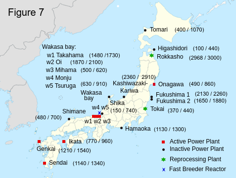 Figure 7 shows (the stored spent nuclear fuel / the storage capacity) (in ton unit) in the cooling pool in each nuclear power plant. In the cooling pool, the loss of electricity will cause the meltdown of the fuel within three days. Therefore the best solution for the storage of the spent nuclear fuel is to use the dry cask. However, a sufficient number of dry casks may not be available immediately. To survive the Nankai Trough Earthquake we may have to use cooling pools with secure electricity and without any risks of tsunami, such as in the north part of Japan and in foreign countries. The spent fuel in Ikata and Hamaoka needs to be stored in the dry casks or to be moved to safer places right now. The spent fuel in the other plants in the south part of Japan also need to be protected in the same way.
In Hamaoka nuclear power plant 1130 tons of spent nuclear fuel is still stored in the cooling pool. According to the homepage of Chubu Electric Power, they increased the earthquake resistance of the facilities up to 1200 gal and added the breakwater.(Chubu Electoric Power [4]) But those are completely useless. Hamaoka nuclear plant is located on the top of the three tectonic plates boundaries. The anticipated earthquake is much, much more fierce than 1200 gal. According to the new damage estimation (NHK [8]), the height of the tsunami in Hamaoka is 20 meters. Hamaoka nuclear plant is about 6 meters above sea level. Even if they consructed 14 meters breakwater, there are no guarantees that it will work. The liquefaction of the ground may occur beneath the breakwater and the actual tsunami may be 30-40 meters. What we have learned from the 2011 Tohoku earthquake is that the only way to survive from a tsunami is just running away from it. In Taro in Iwate, people had constructed a gigantic breakwater of 10 meters high and 2 kilometers long to defend their town, but the actual tsunami came far beyond the breakwater and destroyed it like pudding. Therefore the best solution is to put the spent nuclear fuel in the dry casks and move them to safe places beyond the reach of the tsunami.